
Table of Contents
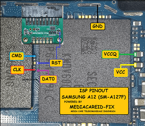
An ISP pinout, or In-System Programming pinout, refers to the configuration of pins on a device that allows for programming, debugging, and testing electronic components. This pinout provides a standardized way for external programming devices to communicate with and control the internal circuitry of the target device, such as a microcontroller or FPGA. Understanding the ISP pinout of a device is crucial for developers and engineers when designing and debugging electronic systems.
Main Points
- Importance of ISP pinout in electronic component programming and debugging
- Standardized configuration for communication between external programming devices and target devices
- Significance for developers and engineers in electronic system design and testing
Understanding ISP Pinout and Its Importance in Hardware Design
The Significance of ISP Pinout in Hardware Development
When it comes to designing hardware, understanding the ISP pinout is crucial for ensuring the functionality and compatibility of the device. ISP, or In-System Programming, pinout refers to the arrangement and connection of pins that allow for programming and debugging of the hardware during the production and testing phase.
It is essential to pay attention to ISP pinout due to its impact on the overall performance and functionality of the hardware. A well-defined ISP pinout layout can facilitate efficient programming and debugging processes. In contrast, a poorly designed pinout can lead to compatibility issues and programming errors.
Critical Aspects of ISP Pinout and its Importance:
- Compatibility with programming tools and software: The ISP pinout layout must be compatible with the programming tools and software used for production and testing.
- Efficient debugging and programming: A well-defined pinout allows for efficient debugging and programming, saving time and resources during development.
- Compatibility with external components: The ISP pinout should be designed to accommodate the connection of external components, such as sensors or actuators, without causing interference with the programming process.
In conclusion, understanding ISP pinout and its importance in hardware design is crucial for ensuring the hardware development process’s functionality, compatibility, and efficiency.
Critical Components of ISP Pinout and Their Functions
In-system programming (ISP) is a crucial process in electronic design and manufacturing, and understanding ISP pinout and their functions is essential for successful programming. There are three critical components of ISP pinout, each serving a specific function:
- VCC (Voltage Supply)
The VCC pin provides the necessary power supply to program the device. Ensuring the voltage levels are accurate is crucial to avoid damaging the device during programming.
- GND (Ground)
The GND pin is the reference point for the voltage supply and signals. It ensures that the electrical potential is grounded and stable, preventing voltage fluctuations during programming.
- ISP Programming Pins
These pins, including MOSI, MISO, SCK, and RESET, are used for data transfer and communication between the programming device and the target microcontroller. Each pin has a specific function in the programming process, and its proper connection is critical for a successful ISP.
| Pin | Function |
|---|---|
| VCC | Provides power supply |
| GND | Reference point for voltage and signals |
| ISP Programming Pins | Used for data transfer and communication |
How to Interpret ISP-Pinout Diagrams
When working with ISP pinout diagrams, it’s essential to understand the structure and layout of the pins to ensure successful programming and communication with the target device. To interpret these diagrams effectively, identify the key components and their corresponding pins. Then, analyze the specific functions of each pin and how they relate to the overall programming process. It’s also essential to consult the documentation provided by the manufacturer for an accurate interpretation of the ISP pinout diagrams.
Common Mistakes to Avoid When Working with ISP Pinout
When working with ISP-pinout, it is crucial to avoid common mistakes that can lead to errors and setbacks in your project. Here are some critical mistakes to steer clear of:
- Incorrect Connections: One of the most common mistakes is making incorrect connections, which can malfunction or damage the ISP pinout.
- Using the Wrong Voltage: Another crucial mistake to avoid is using the wrong voltage, which can also damage and fail the ISP pinout.
- Not Following Datasheet: It is important to always refer to the datasheet. Follow it to avoid errors when working with the ISP pinout.
Tips for Working with ISP-Pinout
Here are some additional tips to ensure successful work with ISP pinout:
- Always double-check your connections before powering on the ISP pinout.
- Use a multimeter to verify voltage and continuity in the connections.
- Refer to the datasheet and follow the recommended guidelines for working with ISP pinout.
By avoiding these common mistakes and following the tips, you can ensure smooth and successful work with ISP pinout for your projects.
The Evolution of ISP-Pinout Standards
In-System Programming (ISP) pinout standards have undergone significant evolution over the years, adapting to the changing needs of the electronics industry. Initially, ISP pinouts were specific to individual manufacturers, leading to compatibility issues and inefficiencies. However, with the standardization efforts of organizations like JTAG and IEEE, ISP pinout standards have become more uniform and widely accepted. This evolution has streamlined the programming process for various devices, ensuring excellent compatibility and efficiency in electronics manufacturing.
ISP-Pinout Testing and Verification Methods
One standard ISP pinout testing and verification method involves using a multimeter to check for continuity and resistance in each pin. This process helps identify any potential issues with the connection or wiring, ensuring accuracy and functionality. An oscilloscope provides a powerful tool for measuring the signal integrity and timing of the pins, enabling a more in-depth analysis. This allows you to determine if the signals meet the specified tolerances. A logic analyzer can provide a detailed view of the data being transferred on the pins, allowing for thorough testing and verification.
Using a Multimeter
Before using a multimeter for ISP-pinout testing, ensure it’s set to the correct continuity or resistance testing setting. Then, you can check each pin individually to identify any open circuits or excessive resistance. This can help identify any potential wiring issues or faulty connections.
Using an Oscilloscope
An oscilloscope can measure the voltage levels and timing of the signals on the ISP pins. This can help determine if the signals are within the specified tolerances and if there are any issues with signal integrity. Any abnormalities or inconsistencies can be identified and addressed by carefully analyzing the waveform.
Using a Logic Analyzer
A logic analyzer can provide a detailed view of the data transferred on the ISP pins. This can help verify that the correct data is being transmitted and received and identify any timing or protocol issues. Any discrepancies or errors can be identified and resolved by capturing and analyzing the data.
| Method | Tools | Benefits |
|---|---|---|
| Using a Multimeter | Multimeter | Identify open circuits and resistance issues |
| Using an Oscilloscope | Oscilloscope | Measure signal integrity and timing |
| Using a Logic Analyzer | Logic Analyzer | Provide detailed view of data transfer |
Integrating ISP-Pinout Considerations into PCB Design
When designing a PCB, it is crucial to consider the pinout of the in-system programming (ISP) interface. Integrating ISP pinout considerations into PCB design can help ensure smooth and efficient programming of the device. Here are some essential factors to keep in mind:
- Pinout Alignment
Aligning the pinout of the ISP interface with the corresponding pins on the microcontroller is critical for successful programming.
- Signal Integrity
Ensuring signal integrity between the ISP interface and the microcontroller is essential for reliable communication during programming.
- ESD Protection
Incorporating ESD protection measures into the ISP-pinout design is crucial for safeguarding the device against electrostatic discharge.
By carefully considering these factors and integrating ISP pinout considerations into PCB design, engineers can optimize the programming process and enhance the device’s overall performance.